5x7 Display
INDEX
![]()
This project
consists of 10 Chapters (and over 20 pages):
Chapter 1 - Index
(this page)
Chapter 2 - Introduction
Chapter 3 - Construction
Chapter 4 - Burning
a Chip also called "Programming" or
"Downloading"
Chapter 5 - Display
Effects a page of .gif files showing the effects you can
produce
Chapter 6 - Testing
The Test Routine and 3 Testing Routines
Chapter 7 -
Experiments 11 Pages of experiments Expts 1 - 28
Chapter 8 - Piezo Experiments
2 pages of experiments Expts 1P - 8P
Chapter 9 - EEPROM Experiments - not yet finished
Chapter 10 -
Programming Starts Here - helpful hints on how to produce a program
|
I have now deleted this project from the CD to
make room for other projects. This project uses the PIC16F84 and a much better chip (PIC16F628) has now been produced by Microchip at a lower cost, with more features. A few kits are still available but some of our other kits are much cheaper and use more up-to-date programming features. This project shows how electronics has advanced over the past 20 years and things are now better, cheaper and smaller. We all have to "move with the tide" and our latest projects are really informative. The whole aim of Talking Electronics is to produce a project at the lowest cost, with the minimum number of components, and the maximum educational content. The only way to get into programming and designing your own projects is to build lots of things. Everything you build, adds to your knowledge. That's how all the staff at Talking Electronics became so knowledgeable. |
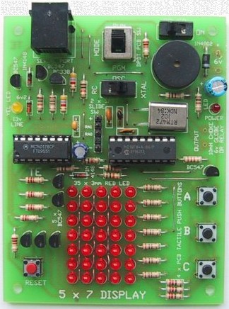
The complete 5x7 Display
A note from a reader:
Your 5x7 display is my favourite toy; the tunes and graphics
in the elevator display always impress my mates!
Since building the display I developed my own 400 dot matrix using a pic and
the SN74154 [4bit binary to 1 of 16 demultiplexer\counter] - in place
of the 4017. It works well but I still have to hook it up to my computer to
change the scrolling message. When I get time I will write
another program that will make it easier to program the message board via an
I.R. remote.
Once again thanks for the project.
Phil Elliott
philjelliott@bigpond.com
Here is an example from a reader who has increased the display to 10x7:
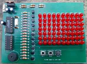
10x7 Display from a reader
Here is another example from a reader who has used the knowledge gained from the 5x7 project to make a very large display:
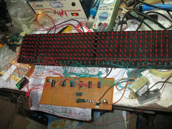
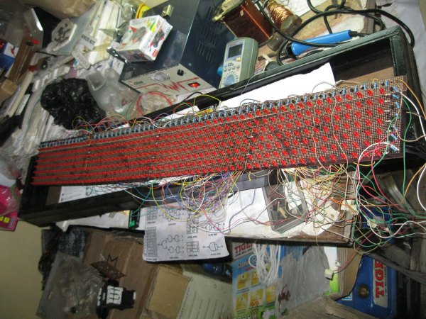
But first you need to build the 5x7, understand
how it works and how to create the programs.
| In
a nutshell, here is what you do: 1. Read the 9 Chapters of the 5x7 Display project 2. Buy and build the 5x7 Display project 3. See: 5x7hexFiles containing all the .hex files. Click on notepad.exe and it will open. Drag any file to Notepad and it will display the hex values! Go to: All 5x7 Files for all files. 4. Get IC-Prog.exe file and move it to your Desktop. See also: IC-Prog help-line and IC-Prog message Board To compile your .asm files to .hex you will need: MPASM If the 5x7 Display does not program correctly on your computer, we have a Multi Chip Programmer project which has a different circuit to create a higher programming voltage from your serial port. 5. Build another project such as the Logic Probe or start designing your own project . . . . your programming world has started. |
If you are starting from "Ground Zero" and know
little or nothing about electronics, go to our BASIC
ELECTRONICS course.
You must be able to recognise components such as capacitors,
diodes, zeners, transistors and resistors to build 5x7
Display project. This information is
covered in our BASIC
ELECTRONICS COURSE and a complete set of circuit symbols can be found
HERE
If you want some simple books on electronics, see our range of Notebooks and
project books by Talking Electronics at:
http://www.talkingelectronics.com
If you have not constructed any electronics projects, you should see the
range of simple kits by Talking Electronics. There are over 200 kits to choose
from and they can be found at:
http://www.talkingelectronics.com
Build at least two or three of these kits to get your hand into soldering
and working with electronics components, before working on the
There is an enormous amount of information from Talking Electronics to get you up to the stage of being able to understand electronics jargon as well as being able to read circuit diagrams and assemble simple projects. Look through this information before starting this project so you can follow our assembly procedure and be assured it will be assembled without the possibility of dry joints or damage to the components. .
The 5x7 Display Project starts you at the beginning with programming but the more you understand about electronics-in-general, the more you will gain from the project.
The project covers three basic areas:
1: The mechanics. The soldering side of the project.
2: The electronics. The creation, reading and understanding of the circuit and creating circuits to suit your own projects.
3: The program. The programming side.
START
HERE:
You are now ready to start.
You will need the
5x7
Display Project. It is available from
Talking Electronics. While you are waiting for your kit to arrive
(It's a same-day mail-out service but the mail may take 2-7 days for
arrival) you can cover the programming section. There's at least 3 days
worth of study in this section and it's all presented on the web with
hyperlinks to each section. You can even go through the experiments before
your kit arrives and become familiar with how the programmes are structured.
It has been shown (Cocoa-Cola research) that it takes three exposures (of
advertising) to get 90% acceptance. The first pass gathers 50 - 80%, the
second pass increases this to 90% and the third pass brings retention to
95%.
With programming you have to be very near 100% if you don't want too many
mistakes in a program. If you have 5 mistakes in a 100 line program, it may
take hours to trouble-shoot.
That's why electronics is a "perfect
science." Things have to be "spot-on" for the project to
work.
So, the more you study, the closer you will be to getting a program
up-and-running the first time.
On some occasions a program has worked the first time. It's most gratifying
and the more you work on your theory, the more chance you have of getting a
routine working. Not only that, increased experience enables you to create
more-complex programs. So it's benefit's all around.
Without any more discussion, here are the steps:
Step
1: Read the Introduction
chapter. It will take you to the
Screen Effects
page where you can see some of the examples that can be created with this
project. Programming
Starts Here - a study of the routines used in this project. Here is a detailed list of the pages shown above,
with
the main Experiments Page1
Expt 1: Turn on a LED. That's all. A LED turns ON Piezo Experiments Page1
Expt 1P: Making a TONE.
Step 6
Step 2: Read
Construction-Part1
chapter. It covers the 5x7 Display section of the circuit including the
PIC chip, the CD 4017 shift-chip, the switches and driver transistors.
Construction-Part2
chapter covers the In-Circuit programmer section of the circuit. These two
circuits are combined on the PC board however they have been described
separately to keep the diagrams simple. These two pages also describe
the assembly of the PC board. You can build the whole
project or just fit the first column of LEDs. The first 6 experiments
require just the first column of LEDs and the other experiments require the
whole screen.
Step 3:
To make sure the project works correctly, we have produced a set of TEST
PROGRAMS. These test the chips, the LEDs and the wiring to the
components. They are intended for those who have built the project on their
own board or "Matrix Board" and need diagnostic tests. They are
not needed if you have put the project together from a kit as the
"experiments" start you at the beginning of programming.
We do not recommend you build the project on Matrix Board as the added work
in wiring up the components is considerable. We had to start in this way as
no board was available but for the cost of a PC board, the final result is
worth the cost. PC boards are available separately from Talking Electronics.
If you want to try the test programs, they are located at:
Testing Page1,
Testing Page2,
Testing Page3.
The project comes with a pre-programmed PIC chip, containing a TEST
ROUTINE.
When the chip is inserted into the project and switched on, it goes through
a number of routines to display each of the LEDs, patterns on the screen and
tones from the piezo. When you program this chip, the Test Routine will be
lost. If you don't want to lose it, you can use another chip for your
programming.
The Test Routine can be found at: Test
Routine.
The only test we have not covered is "Burning." This is the most
important (and most complex) of the tests. The only way this can be checked
is by carrying out an actual burning operation and the first experiment will
do this.
Step 4:
The next step is to burn a routine into the PIC chip. This is done with the
chip "in situ" on the board. That's the advantage of "in
circuit" programming. The chip does not have to be removed from the
board to be programmed.
Simply connect the cable to the serial port of the computer and fit the
4-pin US telephone plug into the 5x7 Display board.
Some of the voltages for the chip are obtained from the computer during programming
mode, but the 5v from the computer does not have enough current to drive the
transistor on pin 12, so the power switch on the 5x7 project must be kept ON
during programming.
The 13v required by the chip to set it into programming mode is obtained
from the serial port of the computer (as a complex combination of the
voltages on two lines!). This arrangement has been necessary so that almost
any serial port will be suitable for connecting to the project.
Before carrying out any "Burning," you need to go to the first page of experiments:
Experiments
Page1 and study the first experiment.
After studying it, you can download the .hex file at the end of the
experiment, by either copying and pasting the block of numbers into a text
program such as TEXTPAD or NOTEPAD and then using the burning program
(called IC-Prog) to load the data into the PIC chip on your 5x7 project.
Alternately you can find all the
5x7.hex files
for the
project and select Expt-1.hex for downloading into the PIC chip via IC-Prog program. For more information see: "Burning
a Chip."
To see the burning program (IC-Prog) click
IC-Prog.exe
Step 5:
As you go through the
experiments, they get progressively more complex. We have produced three
different sets of experiments and you should look through them all and carry
them out "in parallel." In other words you can jump from one group
to the other as they all cover different features and they all need to be
carried out.
Test
Routine. This is the routine that comes in the chip to test
your project.
Testing Page1,
Testing Page2,
Testing Page3.
Experiments Page1
Experiments Page2
Experiments Page3
Experiments Page4
Experiments Page5
Experiments Page6
Experiments Page7
Experiments Page8
Experiments Page9
Experiments Page10
Experiments Page11Piezo Experiments Page1
Piezo Experiments Page2
. . . then go to Expt
27.
features of each experiment / routine:
To see all the .hex files: click
HERE.
Test
Routine. Tests the LEDs on the screen (individually) and
the piezo diaphragm (comes with the PIC chip when purchasing
the kit).
Testing Page1 First column of LEDs flash at 3Hz.
First column scanned from bottom to top.
Bottom LED moves from left to right
Testing Page2, Data from "Ghost" files to
"Display."
"TE MOVING SIGN." Letters are scrolled across display.
Testing Page3. Turns on a LED when button A is pressed.
Detects buttons A, B and C and turns on LEDs.
Buttons A, B and C (with debounce) and LEDs flash.
Expt 2: Flash a LED. A LED flashes at 2Hz
Expt 3: Scan up. LEDs in the first column turn on individually.
Expt 4: Scan up and down.
Expt 5a: Turn on a LED via button A (with poor debounce)
Expt 5b: Turn on a LED via "A" (with switch debounce)
Expt 6: Reaction GAME. LEDs in column 1 turn on individually (up and
down) and button A should be pressed when the centre LED is
illuminated.
Experiments Page2
Expt 7: Column shift right. Each column of LEDs turn on.
Expt 8: Column shift right/left. The column of LEDs shifts back and
forth.
Expt 9: Across/back - up/down. A column of LEDs turns on across the
display then up and down the display.
Experiments Page3 Expt 10: Button A
starts/stops the action of expt 9.
Expt 11: Elevator display. Button A and B cause numbers to go up and
down on the display similar to those in an elevator.
Experiments Page4
Expt 12: "RUNNING SIGN" See Testing Page 2. "TE Moving
Sign." Letters run across the
display.
Experiments Page5
Expt 13: Single Digit Up-Counter. 0-9 Up counter with button A to
increment the display.
Expt 14: Two Digit up Counter. 00-99 Up counter with button A to
increment the display.
Experiments Page6
Expt 15: Five Digit Up Counter. Button A increments the
display.
Expt 15a: Five Digit Up Counter with Reset. Button A increments the
display. Button C resets the count.
Expt 16: Two Digit Up/Down Counter using buttons A and C.
Experiments Page7
Expt 17: Animation-1. A single CELL is displayed on the screen.
Expt 18: Animation-2. Five cells are displayed on the screen.
Expt 19: Animation-3. Wipe-Up turns off the rows of LEDs, from
bottom to top.
Expt 19a: Combines Expt 18 and 19.
Experiments Page8
Expt 20: Animation-4. Five Cell animation then Wipe-Up, then
Wipe-Down.
Expt 21: Animation-5. SLASH. A diagonal line moves up the
screen.
Expt 22: Animation-6. SPLASH. Similar to a stone dropped into a
pond.
Experiments Page9
Expt 23: Press button A for SPLASH - with debounce.
Expt 24: Press button A to Start/stop action. Button A is a toggle
button.
Expt 25: "Bull's Eye." A simple
Hit-the-LED-game.
Experiments Page10
Expt 26: "LED Dice"
Experiments
Page11
Expt 27: "LED Dice with Sound-1"
Expt 28: "LED Dice with Sound-2"
Expt 2P: Producing a BEEP.
Expt 3P: Beep after button A, B and C.
Expt 4P: Hee Haw Siren.
Piezo Experiments Page2
Expt 5P: Calling Hee Haw routine.
Expt 6P: Making a NOTE.
Expt 7P: Creating a SCALE.
Expt 8P: Creating a TUNE.
Programming
Starts Here Page1 - a study of the routines used in this project. You
can access this page at any time and study how the routines are
created. In fact it's a good idea to refer to this page as soon as
you start the experiments.
Programming
Starts Here Page2 - more routines and how they work
If you are like me, you will want to go further and use some of these skills
to produce your own projects. Already you must have a number of ideas that
could be turned into a microprocessor project.
Things like alarms, interfaces, games and counters etc.
And this is where Talking Electronics can help. They have produced a
number of projects and experimental boards suited to
getting you into this next phase of development.
They have produced two streams. The first stream uses the
PIC16F84 as the main chip and the second stream uses a smaller version
called the 12C508A.
Many of the projects you are thinking about will require only a few
input/output lines and the PIC12C508A will be suited for the job.
For instance, if you want to design a small project and have it mass produced,
the cost will have to be as low as possible. This is where the PIC12C508A comes in.
It it less than half the cost of a PICF84 and enables very low-cost projects
to be produced and you will be competitive with overseas imports. It is also
available in surface-mount form so very small projects can be produced. But
it takes lots of steps to get from an idea to the finished design and TE has
the parts, PC boards and ideas to help you.
The only problem with the PIC12C508A is it is not as friendly as the PICF84
and it's only by following our course that you will be able to design
economical projects with it. The PIC12C508A course starts with Chapter
1. Go to this chapter and you are on your way. This chapter will lead
you into hundreds of pages of programming, ideas, projects and theory on
both the PIC12C508A and PIC16F84 and they will keep you up all night for
WEEKS!
Send me an email when you finish!
All the best,
Colin Mitchell,
TALKING ELECTRONICS.

(click on
envelope
to send email)
Note: The
PIC12C508A has 5 port lines - called in/out lines. The only limitation is:
port line GP3 must be input. If you have a project requiring 4
outputs and 1 input (or 3 outputs and 2 inputs etc) - the '508A is the
one to choose. There are ways to expand the lines or put two different
devices on the same line, so read the pages we have produced before
dismissing this amazingly versatile device.
and individual chips, the microcontroller
is equal
to a dozen or more gates, all in
the one package! And
all our programming is
here.